
DLT Engineering
Product Page
Product Page
DLT Hydraulic sling length adjustment system
The DLT Hydraulic sling length adjustment system is intended for use on multi-point lifts where the lifted load at each lifting point must be measured and adjusted to correct for different sling lengths and flexure of lifting beams, and also where it is required to adjust sling lengths to level or align the load.
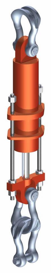
The system is designed to be accurate, safe and reliable. The principle is to use a hydraulic tension ram in each of the sling lengths with a back up mechanical locking system as shown below. Each system is designed and manufactured to order and can be supplied in capacities from 5 tonnes to 2,000 tonnes per ram. The system is modular and comprises the hydraulic tension rams, the power pack(s) and a central computer control system. The power pack(s) are located on the load to be lifted with hose & data connections to the tension rams and data connections with each other. The central control computer has a wireless link to one of the power packs and can be located anywhere within 100m radius of the wireless power pack.
Each ram is fitted with a pressure sensor and stroke encoder with this data being relayed wirelessly back to the central control computer. Prior to starting the lift the operator enters the desired load for each ram into the control computer and the acceptable variation in these loads. The rams are then stroked to the midpoint of their strokes and the lift can commence.
As the crane slowly takes the up the load the DLT hydraulic multi-point lifting system will automatically adjust the individual ram lengths to achieve the desired load distribution between the lifting points, automatically correcting for :
On completion of the lifting operation and just prior to setting the load down onto its supports (or making a connection to a supporting structure) the system can be used to accurately line and level the load. It is not necessary to manually unwind the locking nuts to do this. The tension rams can all be retracted from the control computer to create the necessary clearance to the locking nuts to allow +/- length adjustment at each tension ram for leveling and aligning the load.
- Different sling lengths
- Different sling extensions under load
- Flexure of the lifting beams
- Flexure of the load being lifted
On completion of the lifting operation and just prior to setting the load down onto its supports (or making a connection to a supporting structure) the system can be used to accurately line and level the load. It is not necessary to manually unwind the locking nuts to do this. The tension rams can all be retracted from the control computer to create the necessary clearance to the locking nuts to allow +/- length adjustment at each tension ram for leveling and aligning the load.
